Computer design
Single photon emitter (SPE)
This part of this project might require handling a Class 4 laser. In order to handle such dangerous equipment safety measurements must be in place. So to do that we made a list which includes the following precautions mainly by following UCSB’s and the University of Pittsburgh’s “Laser Safety Manual“
Strive to enclose as much of the beam as possible
Use a controlled access area
Always wear protective eyewear suitable for the lasers frequency range
Make sure that the path of the laser must be parallel to the ground and below eye level for one seated or standing
Try to operate the laser remotely with the use of a switch or an arduino
Install appropriate laser warning signs at the area of the laser’s operation
Mount the laser on a firm support to assure that the beam travels along the intended path
Use a low powered laser Class 1 or 2 laser to simulate the path of the UV one
Use skin protection to protect skin from laser burns or injury
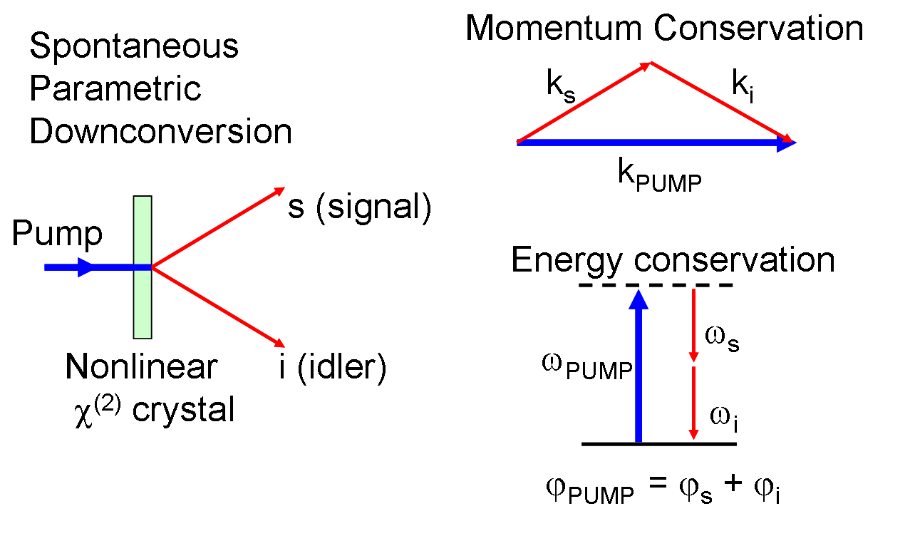
The purpose of the single photon emitter (SPE) is to generate a single photon. While at first constructing such a device from inexpensive components might seem hard the truth is far from that thanks to a phenomenon called Spontaneous Parametric Down Conversion (SPDC). In essence, by using a special nonlinear crystal called KDP (which is relatively inexpensive) SPDC allows us to break a higher energy photon into two lower energy, entangled photons. Unfortunately this effect takes place in only 1 in about a billion photons, so to ensure we have at least one photon in our circuits we need a high powered laser.
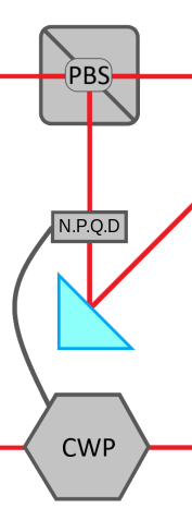
While at glance one might think that we are done with our photon generation there is actually one more step to this process, breaking the entanglement. To do this we have designed a module we call the Disentangling Device. As we briefly said above SPDC creates 2 entangled photons but in order to use those photons in any circuit we need to break their entanglement and set them in the |0⟩ state, that’s where Disentangling Device comes into play. The Disentangling Device is nothing more than two polarized beam splitters, a polarized rotator and some mirrors in order to nondestructively collapse the entanglement between the 2 photons.
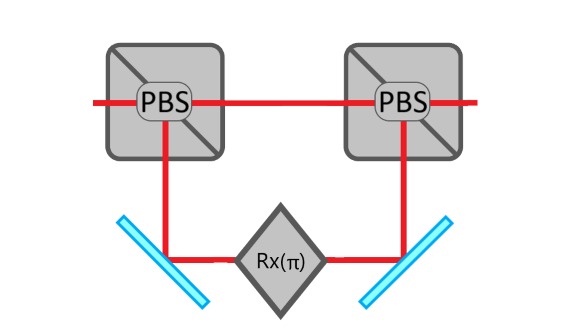
When the photon is entangled and it passes through the PBS, the superposition collapses. If the photon is at the horizontal state |0⟩ it passes through but if it is in the |1⟩ state then it gets reflected, passes through the polarization rotator which changes the polarization into the state |0⟩. After that using a mirror that is placed after the polarization rotator the photon is reflected back into the stream. Then with some cleverly placed mirrors we can direct the photons into any circuit.
Hadamard Gate/Rx(θ)
One of the most fundamental characteristics of any quantum system is its ability to be set into superposition. Superposition is a state in-between the states |0⟩ and |1⟩. Pauli-Θ uses the vertical and horizontal polarization states as |0⟩ and |1⟩ respectively. So in order to make it easier to understand, we define horizontal polarization (θ=0°) as |0⟩ and vertical (θ=90°) as |1⟩. Now, all the gate has to do to achieve superposition is to rotate the vector representing the state as shown below.
In order to do that, we use a polarization rotator to turn the photon from 0° to 45°. In this way, photons get transformed into the equal superposition state which when measured in the base of |0⟩ or |1⟩ have a 50% probability to be in either state. (But, if we measured in the 45° base we would have a 100% probability to be in that state.) Note: The polarization rotator can be turned into any degree imaginable (from 1-89) to alter the probability of each state in the superposition making it also an Rx gate.

Another alternative of using a polarization rotator is the much cheaper polarizer which is commonly found in 3d cinema glasses. A polarizer blocks or allows a photon to pass depending on its polarization angle For example, if a vertical polarizer will block a horizontal photon and vice versa. So in order to implement a Hadamard gate, one would have to use a polarizer rotated by 45°. This however means that only 50% of |0⟩ photons will pass. For this reason, we using this approach only as way to play around with polarization because even though it is extremely cheap, it lowers the computer’s accuracy by a substantial amount.
Controlled NOT Gate (CNOT)
The CNOT is a two qubit gate and it allows qubits to interact with each other. This gate involves 2 qubits, a control qubit and a target one. If the control is in |1⟩ state Then the target qubit gets flipped, but if the control is in |0⟩ then nothing happens and both qubits continue. To implement such a gate in our system we need to use a nondestructive photonic qubit detector (NPQD) and a Controlled Waveplate. Unfortunately as far as we know NPQD’s do not exist yet so we cannot yet design a nondestructive CNOT gate. That said we can make a destructive CNOT using photon detectors like PMTs. All you need to know about the controlled wave plate is that it works exactly as an X gate (bit flip) but only when current is passing though it. Now, let’s revise how this gate works exactly. The control qubit goes through a PBS where it splits down 2 different paths, if its in |0⟩ state, then it just continues to be measured. However if it’s in the |1⟩ state then it gets reflected by the first PBS it gets measured. When the control qubit is measured in the |1⟩ state, current is passes through the controlled wave plate activating it and flipping the the target qubit in the process.